
Abstract
As a result of mathematical modeling it has been shown that any closed electrical line can be interpreted as a ring waveguide where the Fermi-Pasta-Ulam recurrences of the electron and phonon currents interact with each other on the transversal and longitudinal periodical structures of the line conductor’s crystalline lattice as well as on the structures of the wire insulation. An electronic circuit simulating the mathematical model through the dynamics of magnons and phonons in a closed ferrite core with two different coils switched into the shoulders of a multivibrator has been developed. It has been demonstrated that the interacting ferromagnetic and ferroacoustic resonances excited simultaneously in a ferrite core qualitatively correspond to the dynamics of the electron and phonon currents interaction process in a closed electrical line.
Author Contributions
Academic Editor: Loai Aljerf, Department of Life Sciences, Faculty of Dentistry, University of Damascus, Syria.
Checked for plagiarism: Yes
Review by: Single-blind
Copyright © 2019 Berezin A.A
 This is an open-access article distributed under the terms of the Creative Commons Attribution License, which permits unrestricted use, distribution, and reproduction in any medium, provided the original author and source are credited.
Competing interests
The authors have declared that no competing interests exist.
Citation:
Introduction
In the earlier paper 1 there was discussed an idea that an electric current represents a quantum recurrence between the energies of its electron and phonon components. Similar hypothesis was put forward by British scientist Heaviside who supported a concept that the “energy current” propagates in an electrical line not along conductors but in the layers of their insulation 2, 3. The purpose of the study was to work out a mathematical model of an electric current in a transmission line as well as to elaborate a physical device that would support the developed theoretical notions.
Theoretical Model of Electric Current in a Transmission Line
First consider a closed electrical transmission line as a ring waveguide. We define the amplitude of electron current in the transversal plane of the waveguide as Ielectron and the amplitude of phonon current in the longitudinal plane of the waveguide as Iphonon. Using the results of the paper 1 we can describe the interaction process between the two currents within the framework of two parametrically coupled Hill’s type differential equations. Some properties of these equations including their ability to absorb the energy of a random perturbation force were discussed in 4:

………. (1)
Where x -is the longitudinal coordinate along the waveguide and y –is the transversal coordinate across the waveguide, KII, K⊥ - are the longitudinal and transversal spatial frequencies. F1 and F1 - are the random functions reflecting the short and long wave heat oscillations along the conductor lattice correspondingly.
The interaction process between the two currents takes place both on a quantum scale 1 and on a classical one. In order to unify the processes of interaction between electron and phonon currents in the line-waveguide on both high and low frequency levels we made the following substitutions and assumptions. For a quantum scale the energy balance between electrons and phonons in a crystalline lattice of a waveguide can be written like this:

……(2)
The distance a between the neighboring atoms in the longitudinal lattice represents a diffraction slot for an electron current. That brings a dispersion ratio for the electron wave in a form:

…… (3)
Now equalizing the energies of electron and phonon waves and using a quantum ratio p = ℏ k, we can put:

……...(4)
Where x - is the elastic force acting between neighboring atoms, m – is the mass of an atom
For a macro scale we can use the dispersion ratio for electromagnetic waves in a cylinder adjustable waveguide 5 imaging that such a waveguide represents a cylinder in a spherical resonator with an adjustable radius R=y. Considering only a diameter cross section of the sphere, we get:
 …… (5)
And for longitudinal waves in a ring line the dispersion ratio looks like follows:

…….(6)
We can reduce the system (1) to the form in which the interaction process between electron and phonon currents taking place on both short and long spatial scales depends only on the temporal coordinate by means of introducing the time lags. So the new system looks like:

………...(7)

……..(8)
Where T0, T2 are the periods of the time lags.

The functions z(t) and w(t) were introduced as time lag ones to unify the processes of dispersion on short and long scales reflecting the dissipation on the crystalline lattice and its non homogeneity:
For long scale (100-200steps) counting of the system (7) the expression for the frequency

whereas for shot scale (10 -20 steps) counting it looks like

since a small section of the transmission line in the transversal plane can be considered as a resonator excited by a number of sources consisting of vertical chains of atoms in the crystalline lattice 5.Exponential parametric multipliers in (7) come from the mutual transformation process between the energies of the electron and phonon currents.
Computer Study of the Electric Current Model
Computer study of the model system (7) shows that on a ring scale (100 steps and more) the dynamics of the currents demonstrates a resonant interaction between their Fermi-Pasta-Ulam recurrences 6 since they are formed on the periodical structures of the crystalline lattices. Figure 1 shows one of the forms of the FPU interacting recurrences appearing in the dynamics of the phonon current whereas Figure 2 depicts same for the electron current., Figure 3,Figure 4, demonstrate some middle states of both FPU recurrence and Figure 5,Figure 6 - the return to the initial states.
Figure 1.Initial Fourier image of the Iphonon in a number of solutions of (7) on a long scale. Vert. axis – amplitude, horiz. axis – time (units are conditional)
Figure 2.Initial Fourier image of the Ielectron in a number of solutions of (7) on a long scale. Vert. Axis-amplitude, horiz. Axis-time (units are conditional)
Figure 3.Middle Fourier image of the Iphonon in a number of solutions of (7) on a long scale. Vert. axis – amplitude, horiz. axis – time (units are conditional)
Figure 4.Middle Fourier image of the Ielectron in a number of solutions of (7) on a long scale. Vert. axis – amplitude, horiz. axis – time (units are conditional)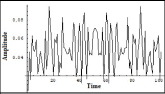
Figure 5.The recurrence of the initial Fourier image of the Iphonon in a number of solutions of (7) on a long scale. Vert. axis - amplitude, horiz. axis – time (units are conditional)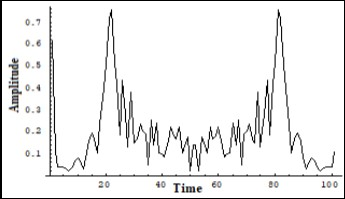
Figure 6.The recurrence of the initial Fourier image of the Ielectron in a number of solutions of (7).on a long scale. Ver. axis – amplitude, horiz. axis – time (units are conditional)
Computer study of the electric current model system (7) along a restricted part of the waveguide (10-20steps) shows a presence of the FPU recurrence only in the dynamics of the electron current (Figure 8,Figure 10,Figure 12). Whereas the frequency dynamics of the phonon current remains stable on a restricted length of the waveguide (Figure 7,Figure 9,Figure 11). Mentioned groups of graphs were obtained during a number of different runs of the system (7) on a computer.
Figure 7.Unchangeable Fourier image of the Iphonon in a number of solutions of (7) on a short scale. Ver. axis – amplitude, horiz. axis – time (units are conditional)
Figure 8.Initial Fourier image of the Ielectron in a number of solutions of (7) on a short scale. Vert. axis – amplitude, horiz. axis – time (units are conditional)
Figure 9.Unchangeable Fourier image of the Iphonon in a number of solutions of (7) on a short scale. Ver. axis – amplitude, horiz. axis – time (units are conditional)
Figure 10.Middle Fourier image of the Ielectron in a number of solutions of (7) on a short scale. Vert. axis – amplitude, horiz. axis – time (units are conditional)
Figure 11.Unchangeable Fourier image of the Iphonon in a number of solutions of (7) on a short scale. Ver. axis – amplitude, horiz. axis – time (units are conditional)
Figure 12.The recurrence of the initial Fourier image of the Ielectron in a number of solutions of (7) on a short scale. Ver. axis – amplitude, horiz. axis – time (units are conditional)
Some more graphs were obtained during the study of the system (7) under different initial conditions for Ielectron and Iphonon. For convenience of comparing with experimental oscillographs there are placed later in the paper.
Experiment
The main purpose of experiment was to visualize the results of the theoretical model through a physical simulation of the system (7). First it was interesting to observe a resonant interaction between two FPU recurrences in the dynamics of the electron and phonon currents obtained as a result of the computer study of the system (7) on a long and short scales of counting (Figure 1, Figure 2, Figure 3, Figure 4, Figure 5, Figure 6, Figure 7, Figure 8, Figure 9, Figure 10, Figure 11, Figure 12). Since the real frequencies of the currents are determined by the scale of the crystalline lattices and lie in a band of 1013 - 109Hz it was decided to use a closed ferromagnetic core with two different coils as a model of a transmission line. For that purpose there was used a commercial fly back transformer (Figure 14) which coils were switched into the multivibrator’s shoulders (Figure 13).
Figure 13.Electronic circuit physically modeling system (7). T1- standard fly back transformer with a closed ferrite core L1 has 12 turns, L2has 400 turns, C1 - air variable capacitor, C2 - 800 pF, C3 -0.25 μF, V1 V2 - transistors of NTE33 type.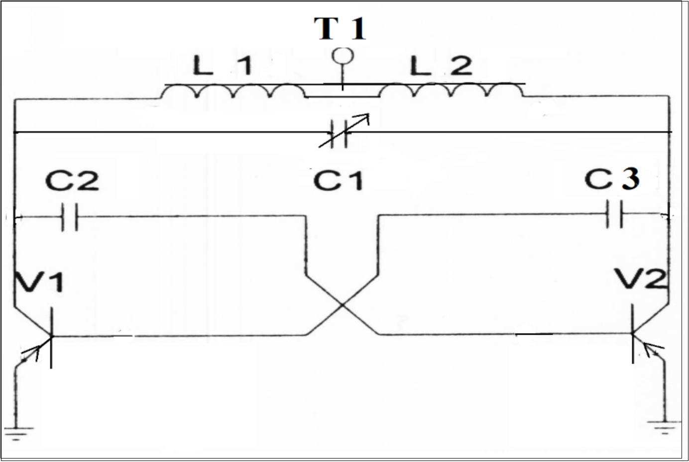
Figure 14.Commercial fly back transformer used in the experiment (Fig.13). Left coil (12 turns) served for simulation of the electron current Ielectron whereas the right one (400 turns) served for simulation of the phonon current Iphonon.
Two resonant processes of transformation of photons into magnons under a ferromagnetic resonance 7 as well as magnons into phonons under ferroacoustic resonance 8 were used as main parameters of the physical model. Consider the details of this approach. As it is known the magnetizing vector dynamics of a ferromagnetic is described within the framework of the Landau Lifshitz 9 equation which in one dimensional case looks as follows:

……(9)
Where the density of the spin energy is9:

……..(10)
And the current density is:

….(11)
As it was shown 9 the equation (9,10,11) can be reduced to the non linear Shrodinger equation having the following solution for E and j :

…… (12)
Where as a result of transformation of the vector to

the Serre-Frene vectors x - is the curvature and 𝜏- is twisting. The expressions (12) represent the canonical forms of the non linear Shrodinger equation solution and mean that in the periodical structure of a crystalline lattice there will be a number of solutions for the current j. As it was demonstrated theoretically 10 and experimentally 11 that the dynamics of the solution of the non linear Shrodinger equation manifests the Fermi-Pasta-Ulam recurrence. In order to visualize such a solution for our model of electric current it was necessary to lower the frequency which was the order of 1013 Hz. That could be possible to provide a transformation of photons into magnons in a ferromagnetic. Any ferromagnetic has a magnetic moment which can have a certain precession. The frequency of such precession usually is a few megahertz. At the same time the frequency of the magnetic moment ω is the energy of a staying magnon 8.
 ….. (13)
Eq. (13) means that under a ferromagnetic resonance a photon transforms into a magnon. The energies of a photon and a magnon are equal with the same impulse:

which gives a following equation:
 …..(14)
Where m* is the effective mass of a magnon:
 …..(15)
The electron mass has been introduced into the (15) for better evaluation. So when Tc ≈ 102 K
The magnon has an effective mass close to that of an electron. If to apply a magnetic field to the ferromagnetic and when μH = kT and H = 104oersted, then the magnon velocity V0 = (Ԑ0 / 2m*)1/2will be V0 ≈ 3x105 cm/sec
This evaluation means that it is possible to “observe” the picture of the non linear Shrodinger equation together with the FPU recurrence just by exciting in a ferrite core a transversal magnetic wave by an electric impulse in a coil having a small number of turns. It was realized by a symmetric multivibrator circuit (Figure 13) in one shoulder of which there was switched the above mentioned coil L1of 12 turns d=1mm wire on a ferrite core of the fly back transformer (Figure 14). The other shoulder was loaded by a coil having the same numbers of turns which was not on a core but in the air. The resulting impulse is shown in Figure 16. As it can be seen its form is close to the non linear Shrodinger equation solution and corresponds to one of the computer solutions of the current model system (7) shown in Figure 15.
Figure 15.One of the solutions of the system (7) for the electron current Ielectron corresponding to the non linear Srodinger equation solution. Vert. axis –amplitude, horiz –time (units are conditional).
Figure 16.Oscillograph of the collector voltage in the physical model of the system (7) with two identical coils in two shoulders of the multivibrator – one on the ferrite core, the other – in the air.(Fig.13). Corresponds to the solution of (7) in Fig.15.Vert axis μsec/cm , Horiz axis-2volts per cm.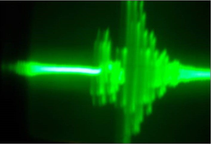
On the other hand the dynamics of the phonon current along the ring waveguide in the structure of the crystalline lattice by analogy with sound waves can be described within the framework of the Korteveg de Vries equation 12. That brings the problem to the Fermi-Pasta-Ulam recurrence first described by Zabusky and Kruskul 13 who have demonstrated that periodical initial conditions in a ring chain described by the KdV equation can result in manifestation of some specific dynamics of the KdV equation solution. For that study there was used the same fly back transformer (Figure 14) with two coils in 12 turns (left in the Figure 14) and in 400 coils (right in the Figure 14) switched into the shoulders of the multivibrator (Figure 13). Between the collectors of the transistors (Figure 13) there was switched an air variable capacitor C1 which played the role of a variable spatial waveguide. with periodical structure. This circuit realized interacting of the two FPU recurrences: one within the framework of the non linear Shrodinger equation 11 and the other – within the KdV equation 13. The KdV solution was obtained in the dynamics of electrical signal on the high voltage coil (right in the Figure 13) of the fly back transformer (Figure 14). The oscillograph in Figure 18 shows a typical solution of the KdV equation which corresponds to one of the solutions of the system (7) shown in Figure 17.
Figure 17.One of the solutions of the system (7) for the phonon current Iphonon corresponding to the solution of the KdV equation. Vert. axis –amplitude, horiz –time (units are conditional).
Figure 18.Oscillograph of the collector voltage in the physical model of the system (7) corresponding to the solution of the KdV equation. Vert axis milli sec/cm, Horiz axis-3volts per cm.
Differently loaded both shoulders of the multivibrator (Figure 13) simulate the two unified solutions of the non linear Shrodinger equation and that of the KdV equation. As in can be seen on the graphs (Figure 20,Figure 21,Figure 23,Figure 26,Figure 29) the two solutions are unified in the experimental circuit. Dependently on the position of the variable capacitor C1 (Figure 13) there prevailed either the KdV solution (Figure 20,Figure 21) or the non linear Shrodinger one (Figure 23,Figure 26,Figure 29.). These graphs correspond to the different solutions of the system (7) under different initial conditions (Figure 19, Figure 22, Figure 23, Figure 24,Figure 25,Figure 27,Figure 28 correspondingly). So the two resonantly interacting FPU recurrences describing the dynamics of the electron current or the phonon current of the model can be in a high frequency part of the FPU spectrum or in a low frequency one developing a new FPU recurrence in accordance with the laws of the interaction between FPU recurrences 6. In terms of an electric current that means that there can be a large current circuit or a high voltage one. It has to be emphasized that working for about five minutes in the high frequency spectrum of the FPU recurrence that is mostly in a region of the Shrodinger equation solution (Figure 25,Figure 26 ) caused an irreversible damage of the circuit including mains transformer, rectifier circuit, both transistors, feedback capacitors and all light diode indicators. But a very surprising subsequence of the experiment was a partial burning of the mains cord and a durable glowing of the cord’s insulation at a distance over 10 meters from the experiment place accounting that the consumed power of the model circuit didn’t exceed 10 watts.
Figure 19.One of the solutions of the system (7) for the sum of the phonon current Iphonon and electron current Ielectron corresponding to the snapshot of the interaction of the FPU recurrences – formed on the transversal structure of the crystalline lattice (non linear Shrodinger equation solution) and formed on the longitudinal structure of the crystalline lattice (the KdV equation solution). Vert. axis –amplitude, horiz –time (units are conditional).
Figure 20.Oscillograph of the voltage on both transistors collectors in the physical model of the system (7) corresponding to the interaction process between two FPU recurrences corresponding to the interaction dynamics of the electron current Ielectron. and that of the phonon current Iphonon . The phonon current energy prevails. Vert axis milli sec/cm, Horiz axis-3volts per cm.
Figure 21.Oscillograph of the both transistors collector voltage in the physical model of the system (7) corresponding to the interaction process between two FPU recurrences corresponding to the interaction dynamics of the electron current Ielectron and that of the phonon current Iphonon. The electron current energy prevails. Vert axis milli sec/cm, Horiz axis-3volts per cm.
Figure 22.One of the solutions of the system (7) for the sum of the phonon current Iphonon and electron current Ielectron corresponding to the snapshot of the interaction of the FPU recurrences – formed on the transversal structure of the crystalline lattice (non linear Shrodinger equation solution) and formed on the longitudinal structure of the crystalline lattice (the KdV equation solution). Corresponds to the balanced case. Vert. axis –amplitude, horiz –time (units are conditional).
Figure 23.Oscillograph of the both transistors collector voltage in the physical model (Fig.13) of the system (7) corresponding to the interaction process between two FPU recurrences corresponding to the interaction dynamics of the electron current Ielectron. and that of the phonon current Iphonon. Corresponds to the balanced case.. Vert axis milli sec/cm, Horiz axis-3volts per cm.
Figure 24.One of the solutions of the system (7) for the sum of the phonon current Iphonon and electron current Ielectron corresponding to the snapshot of the interaction of the FPU recurrences – formed on the transversal structure of the crystalline lattice (non linear Shrodinger equation solution) and formed on the longitudinal structure of the crystalline lattice (the KdV equation solution). Corresponds to the prevailing of the electron current energy. Vert. axis –amplitude, horiz –time (units are conditional).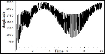
Figure 25.One of the solutions of the system (7) for the sum of the phonon current Iphonon and electron current Ielectron corresponding to the snapshot of the interaction of the FPU recurrences – formed on the transversal structure of the crystalline lattice (non linear Shrodinger equation solution) and formed on the longitudinal structure of the crystalline lattice (the KdV equation solution). Corresponds to the to the prevailing of the electron current energy. Vert. axis –amplitude, horiz –time (units are conditional).
Figure 26.Oscillograph of the both transistors collector voltage in the physical model of the system (7) corresponding to the interaction process between two FPU recurrences corresponding to the interaction dynamics of the electron current Ielectron. and that of the phonon current Iphonon. Corresponds to prevailing of the electron current. The pulse has a complex intrinsic structure of the high frequency FPU recurrence (few GigaHertz). Vert axis 0.5 μ sec/cm, Horiz axis-2volts per cm.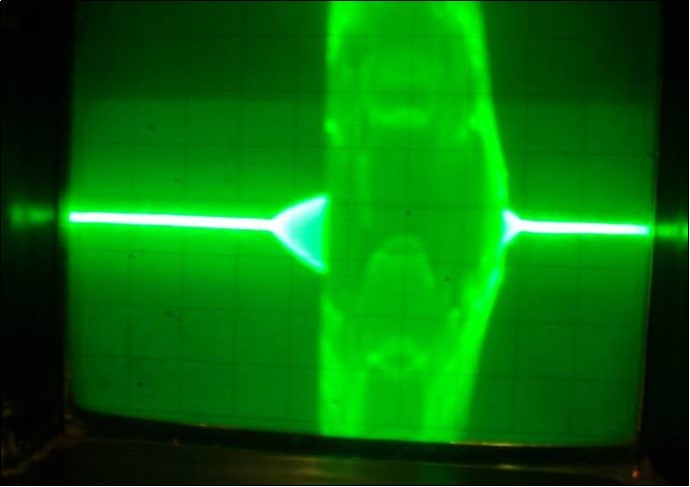
Figure 27.One of the solutions of the system (7) for the sum of the phonon current Iphononand electron current Ielectron corresponding to the snapshot of the interaction of the FPU recurrences – formed on the transversal structure of the crystalline lattice (non linear Shrodinger equation solution) and formed on the longitudinal structure of the crystalline lattice (the KdV equation solution). Corresponds to the to the prevailing of the electron current energy and a long period of longitudinal dynamics. Vert. axis –amplitude, horiz –time (units are conditional).
Figure 28.One of the solutions of the system (7) for the sum of the phonon current Iphonon and electron current Ielectron corresponding to the snapshot of the interaction of the FPU recurrences – formed on the transversal structure of the crystalline lattice (non linear Shrodinger equation solution) and formed on the longitudinal structure of the crystalline lattice (the KdV equation solution). Corresponds to the to the balanced case of both currents energies and a long period of longitudinal dynamics. Vert. axis –amplitude, horiz –time (units are conditional).
Figure 29.Oscillograph of the both transistors collector voltage in the physical model of the system (7) corresponding to the interaction process between two FPU recurrences corresponding to the interaction dynamics of the electron current Ielectron . and that of the phonon current Iphonon. Corresponds to prevailing of the electron current. The pulses have a complex intrinsic structure of the high frequency FPU recurrence (few Gigahertz). Vert axis 1.5 μ sec/cm, Horiz axis-1volt per cm.
Results
The research has resulted in developing a mathematical model of an electric current in a closed transmission line. The waveguide approach used in modeling pointed at a much more sophisticated nature of an electric current than it has been generally assumed. An electric current either AC or DC represents within the framework of the proposed model a complex resonant interaction process between the dynamics of the transversal electron current and longitudinal phonon current in the structure of a conductor as well as in an insulation layers. A physical model developed for evaluating possible solutions of the mathematical model allowed to propose a basis for constructing the FPU recurrence generators that were later used for medical purposes.
Discussion
The problem of interaction of nonlinear resonances has always been a sophisticated one. The more complex proved to be the analysis of interaction between the spectra of the FPU recurrences 6. The first mathematical modeling of two parametrically coupled temporal and spatial electromagnetic waves 4 showed their unusual property of interacting its solutions with the white noise that induced the further research in the sphere. .So, the developed mathematical model of an electric current in a transmission line as well as the elaborating a physical model of this process based on interacting ferromagnetic and ferro acoustic resonances allowed to analyze the problem in a more profound way/ And the quantum mechanic consideration of the electric current phenomenon 1 proved to be helpful for developing of the two interacting electron and phonon currents model.
Conclusion
According to developed mathematical and physical models, a considerable regrouping of energy in favor of the electron current takes place in current transformers, in electrical motors, in the points of wire connections, in the structure of heating alloys whereas the phonon current is characteristic for lightning and for some Tesla’s long distance experiments when the frequency of generated electrical current lied in a band of hundreds of kilohertz. The electron current mode in a transmission line causes prevailing of a high frequency FPU recurrence not only in a conductor but in the insulation material as well, which could result in considerable damage of the electrical networks.
Acknowledgements
The author is thankful to the museum of Russian composer Piotr Chaykovsky in Klin Moscow Region which visiting has helped him to insight the idea of the electric current experimental model. The author is also thankful to the library of Princeton University for help.
References
- 1.Berezin A A. (2019) Does an electric current have an acoustic component?. , Journal of Energy Conservation/ 1(2).
- 4. (1988) Theoretical simulation of a coherent coupled electromagnetic wave structure induced by the white noise. , Physica Scripta 38, 719-720.
- 6.Berezin A A. (2004) Resonant interaction between the Fermi-Past-Ulam recurrences. , Bulletinof Lebedev’s Institute of Physics, n 3, 41-50.
- 9.L A Tachtajan. (1977) Integration of the continuum Heisenberg chain through the inverse scattering method. , Phys. Lett. A 64(2), 235-237.
- 10.P G, Kolovskii. (1984) . (in Russian) , Journal of Experimental and Theoretical Physics (JETP) 60, 1116.
- 11.Yuen H, Lake B. (1978) Non-linear Wave Concept Applied to Deep Water Waves. in Solitons in Action. , New York