
Abstract
Combustion of fossil fuels provides around 88% of total energy supply for modern society, and meanwhile causes many environ mental problems and social problems such as air pollution and energy crisis. Therefore,both at home and abroad are focusing on the research and development of natural gas engine recently. However, the mass production and application of this kind of engine are restricted by some unsolved technical difficulties. This paper explored the injection, combustion and emission processes of diesel/ natural gas and dual fuel engine based on Chemkin II, Fire software and Schlieren method. The experimental study on the mixing process of dual fuel jet was carried out by using high-speed Schlieren method in a constant volume bomb. Based on the Fire software, and then applied to Chemkin II software to analyze the effect of the initial temperature and pressure on the net heat production and combustion emissions. The results show that Dual fuel mechanism is capable of producing different heat production behaviors when varying the initial pressure and temperature CO2 emissions are minimized by changing the initial pressure above or below the atmospheric value. However, CO emissions are peaked when diesel fuel is used. The dual fuel engine minimizes the CO emissions amount caused by diesel fuel. Increasing the initial pressure eliminates dual fuel CO2 combustion emissions. The research of this paper is important to optimize the in cylinder combustion processes of natural gas engine, and have a certain important meaning to guide the development of diesel ignition dual fuel engine.
Author Contributions
Academic Editor: Loai Aljerf, Department of Life Sciences, Faculty of Dentistry, Damascus University
Checked for plagiarism: Yes
Review by: Single-blind
Copyright © 2018 Tasneem Abdalla. et al.
 This is an open-access article distributed under the terms of the Creative Commons Attribution License, which permits unrestricted use, distribution, and reproduction in any medium, provided the original author and source are credited.
Competing interests
The authors have declared that no competing interests exist.
Citation:
Introduction
Although tremendous studies on alternative energy solutions such as combined fuels and hybrid-engines have been under focus for many years, yet there’s still a lack of a complete substitution of the conventional internal engines 1,2,3,4,5. Therefore, conventional engines are employed through a lot of applications to utilize the engine’s optimum conditions 6. Internal combustion engines generally are nominated to reduce the emissions amount below the emissions regulations. Commonly, conventional diesel engines are modified to work as dual fuel engines in which methane fuel provides most of the chemical energy while diesel fuel plays a main role in a pilot ignited one with the methane-air mixture 7,8,9,10,11. However, adding the natural gas fuel option as a supplement for conventional diesel fuel proved that it’s not only a very clean choice but also its more economically viable12,13,14,15. Combining these two types of fuel will elevate the conventional diesel engine’s heating value, lower the fuel cost, and reduce the engine’s adiabatic flame temperature 10,16,17. Most of the existed conventional diesel engines can be modified to serve as dual fuel engines maintaining its compression ratio with less emissions of NOx and particles 13, 14. However, adding methane fuel to the engine makes it more competitive in terms of fuel air mixing and knocking resistance 18.
Recently, the natural gas/diesel combined fuel engine’s implementations have been under focus both theoretically and experimentally to specifically understand the reaction nature 15, 19, 20. The natural gas/diesel fuel ratio, the natural gas initial percentage and the natural gas initial composition with their initial temperatures and pressures conditions were studied and evaluated taking in consideration the intake air temperature 15, 21, 22.The most significant drawback of the dual fuel engines compared with the conventional diesel engine is represented in efficiency redundancy in addition to higher CO emissions in case of low fuel loads 23, 24. At high and intermediate loads both of the engine’s output and CO emissions are better than those in the conventional diesel engines 20, 23, 24. Changing the engine parameters, increasing the pilot fuel amount and changing the injection time might have a better effect on the engine’s output along with CO and HC emissions. However, it also increases the effect on NOx emissions 20, 25.
Many efforts have been made toward overcoming these drawbacks and reducing NOx emissions at the same time. Exhaust gas recirculation (EGR) was suggested 18. The main objective of this study is to explore the injection, combustion and emission processes of diesel/ natural gas and dual fuel engine based on Chemkin II, Fire software and Schlieren method. The complete measurements options for the initial pressure and temperature were conducted for various engines operating mode; particular analysis were conducted on the combustion process such as the engine’s efficiency along with all the associated emissions. For further tests, a high digital CCD in-cylinder camera FASTCAM was used to observe the combustion development. Injection images were post-processed then numerical calculations were obtained using Chemkin II software.
Experimental and Numerical Simulation Study
In this paper, the experimental study on the mixing characteristics of dual fuel injection is carried out by high speed filming combined with constant volume bomb. In order to acquire more accurate and reliable results; three-dimensional numerical simulation of dual fuel iscarried out as shown in Figure 1.The AVL-Fire software used in this article is a CFD software - developed specifically for the engine - is widely used in the engine spray cylinder, combustion and emission simulation studies.
Figure 1.View of the experimental layout (left) and the fuel injectors of the engine (right).
Application of Fire software
Fire software is software developed by AVL in Austria for the study of complex transient flow and combustion problems in the cylinder. The software has a powerful function of solutions and calculations; therefore it has been widely recognized in the field of the engine. Comparing with Fluent, Converge and other similar software, it has the advantages of: (1) The user is simple, clear, easy to operate and efficient; (2) Advanced pre-processing FAME mash generator which can automatically generate hexahedral mesh, and simplify the use of the FAME mash generator;(3) It has provided a technique for solving any shape polyhedron mesh;(4) In addition to the commonly used turbulence model, it can also provide a k-ζ-f compound turbulence model; (5) Its flow model has the highest level in the same software, and the interaction between multiple phases can be calculated.
 Eq.(1)
 Eq.(2)
 Eq.(3)
Where ρ denotes the force on the fluid, μ is the dynamic viscosity, Su, Sv and Sw are the source term.
Mass Conservation Equation
The increase of fluid mass is equal to the mass of the inflow into the fluid in unit time:
 Eq.(4)
In which, t is the time, ρ is the density, u, v and w are the velocity vector components of u in the x, y and z directions.
Energy Conservation Equation
The increase of the energy in the fluid is equal to the sum of the net heat flow and the external force on the fluid in unit time. The energy conservation equation is:
 Eq.(5)
In which T is the temperature, Cp is the Specific heat capacity, k is Heat transfer coefficient, ST is the source term.
Physical Model and Research Program
The physical model is a conceptual model modeled by small or large species, which allow visualization, from examining the model, of information about the thing the model represents. The physical model investigates the geometry of the model and the mathematical correlations applied in this model:
Geometric Model of Constant Volume Bomb
A cylindrical constant volume bomb is used in the experiment, the structure is simple, and the location of the nozzles, size, direction and other parameters in the simulation process were directly defined. Therefore, geometric model of constant volume bomb and meshing is directly built in the Fire software, as shown in Figure 2.The volume of the constant volume bomb is larger, The mixing process of diesel spray, natural gas jet and diesel jet mainly occurs in the center area of the constant volume bomb. In order to shorten the calculation time and ensure the accuracy of the calculation results, the center of the constant volume bomb center is refined. The surrounding area grid size is about 3.5 times than the volume of the encrypted location grid, and the total number of meshes is 120393, which belongs to the structured grid.
Figure 2.the mash of constant Volume Bomb.
Mathematical Model and Boundary Condition
For natural gas jets, there will be an incomplete expansion phenomenon under very high ejection pressure conditions; the jet process is very complex therefore; in this paper, the Pure Gas Jet model is selected as the gas jet model and KH-RT is the broken model. Because the injection mixing process of natural gas/diesel dual fuel in the fixed volume is researched in this section, it does not involve the combustion process. The ambient temperature is represented by the room temperature; the collision model Walljet2 is suitable for the cold wall.
Analysis of Mixing Process of Natural Gas / Diesel Dual Fuel Injection
In order to be able to analyze the mixing process of natural gas/diesel injection the following must be investigated;
Experimental and Numerical Simulation Conditions
This section mainly studies the effect of the ambient pressure on the mixing characteristics of dual fuel injection, so the numerical simulation and the parameters of the experiment are consistent by varying the ambient pressure. In this paper, four different ambient pressures of 0.1MPa, 0.3MPa, 0.5MPa and 1MPa were selected and analyzed. Table 2. gives several major parameters in the study.
Table 2. Basic parameters of experimental and simulation.| The parameters name | The parameters value |
|---|---|
| Diameter of diesel nozzle /mm | 0.16 |
| Diameter of nature gas nozzle/mm | 1 |
| Ambient gas | N2 |
| Ambient temperature/k | 293 |
| Ambient pressure/MPa | 0.1,0.3,0.5,1 |
| Injection pressure of nature gas/MPa | 5 |
| Injection duration of nature gas/ms | 1.5 |
| Injection pressure of diesel/MPa | 40 |
| Injection duration of diesel/ms Phase difference of nature gas and diesel/ms | 0.7 |
The Influence of Ambient pressure on Natural Gas / Diesel and Dual Fuel Jet Development
The pilot ignited diesel fuel is introduced inside the combustion burning chamber as illustrated in Table 1. High digital CCD in-cylinder camera FASTCAM was established to observe the dual fuel combustion development. Photos were taken under different time zones. The results are compared with the results from fire software simulation.
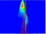
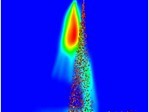
Table 1 shows the dual fuel jet image with different injection back pressure at 0.3ms, 0.5ms, 1.0ms, 1.5ms, and 2.0ms. As can be seen from Figure 3, the numerical simulation is carried out under different back pressure of the diesel and natural gas jet development process and the results are very consistent with the experimental. Because diesel is in a liquid phase and natural gas is in a gas phase, the density and momentum of diesel is much larger than the density and momentum of natural gas, resulting in the consequence that diesel is growing much faster than natural gas in simultaneous injection of two fuels. Backpressure has a great impact on the development of diesel jets and natural gas jets.
Figure 3.Comparison of predicted net production heat using different types of fuels at the beginning of the combustion from time 0.00 till 1.60E-01 second when p=1 atm, T= 297.
| time TheExp. And Simulation. Spray | 0. 3ms | 0.5ms | 1.0ms | 1.5ms | 2.0ms |
| The experiment at 0.1 Mpa |  |
 |
 |
 |
 |
| The simulation at0.1 Mpa |  |
 |
 |
 |
 |
| The experiment at 0.3Mpa |  |
 |
 |
 |
 |
| The simulation at 0.3Mpa |  |
 |
 |
 |
 |
| The experiment at 0.5Mpa |  |
 |
 |
 |
 |
| The simulation at 0.5Mpa |  |
 |
 |
 |
 |
| The experiment at 0.7Mpa |  |
 |
 |
 |
 |
| The simulation at 0.7Mpa |  |
 |
 |
 |
 |
The Chemical Kinetics Model Prediction using Chemkin II Software:
By utilizing the surface reactions dynamics theories for the dual fuel reactions applying the multi-step reaction; a mechanism of 5125 step with 1194 species were obtained. The dual fuel reaction prediction was simulated using Chemkin II software; the predicted dual fuel selected 50 first dual fuel reaction pathways were to indicate the whole reaction’s paths are illustrated in the supporting material Table 1S Which were adopted from Zhang et al. dual fuel mechanism 26.Table 4
Table 4. Chemkin II software simulation bases.| Reaction type | Normal Reflected Shock reactor |
|---|---|
| The Reactor End time | 1 second |
| The reactor incident velocity | 100,000 cm/sec |
| Percentage of N2 in the reaction | 0.7 |
| Percentage of O2 in the reaction | 0.2 |
| Reactant species in Methane fuel case | CH4 : 0.1 |
| Reactant species in Diesel fuel case | Diesel : 0.1 |
| Reactant species in Dual fuel case | CH4:0.09 (90%) Diesel: 0.01 (10%) |
The Combustion Simulation Model:
Reflected shock tube ignition is chosen to validate the combustion reaction mechanisms. This choice was made from several measurements using a range of diagnostics and a variety of shock tubes, fuels, and initial conditions. With the wide selection of the mechanisms available, it is useful to realize that not all of the data are of all the same type or quality, nor are all the mechanisms suitable for simple, direct comparison with the predictions of reaction paths. We apply a comparison of some guidelines for the shock tube ignition with reaction mechanism modeling; shock tube constant-volume behavior; shock tube diameter and boundary layer effects; carrier gas and impurity effects; and future needs and challenges in shock tube research.
Shock Tube Constant Volume Behavior
In comparing modeled ignition data with experimental data, the model calculations are usually done with a constant volume or constant density constraint. One measure of the validity or suitability of this assumption is a comparison of modeled and experimental pressure jump and plateau pressures during and after ignition.
The Shock tube pressure has a range of traces of fuel concentrations from literature review 14. These traces have a several identifiable features. The first plateau is the filling pressure P1, the second plateau is the pressure behind the incident shock P2. The pressure transducer in these experiments was placed2 cm from the end wall of the shock tube, resulting in a short intervals represented in 65s order where this incident shock pressure can be measured. The third plateau is the reflected shock pressure P5. The rapid raise in the pressure at ignition in the highest concentration examples, 0.5% and 0.25% fuel and 0% is the constant volume ignition pressure increase. The ragged form of the experimental pressure data after this time is evidence of a blast wave or detonation that occurs after this pressure jump. In the lower concentration examples, the post-ignition plateau pressures are similar to P5 and the ignition pressure jump is barely noticeable. At times longer than 2 ms in all of these traces, the pressure begins to fall because of the interaction of the driver wave with the reflected shock region27.
If the shock tube reactor were an ideal constant volume reactor, then even with the energy release process occurring during ignition, the modeled pressure along with the measured pressure would achieve the same levels during the initial ignition pressure jump and the final resting plateau. The ignition pressure jump there for can be determined by the energy release rate of the ignition process, and the final resting pressure is determined by the energy that is released. A comparison of the experimental and modeled ignition pressure indicates that at higher fuel concentrations; the pressure jump is substantially less than that predicted by the constant volume model, which is indicative of a failure of the constant volume constraint during the last stages of these energetic ignition events.
Results and Discussion
The results of the numerical simulation using Chemkin software investigating the mechanism of natural gas fuel, diesel fuel and dual fuel combustion as investigating the net heat production of combustion paying great attention to the effect of both initial temperature and pressure along with their related pollutant emissions behavior are reported as follow:
The Net Heat Produced Applying the Three Types of Fuels:
Unlike the in-cylinder pressure estimation based on diesel mechanism and Zheng and Yao mechanism, diesel mechanism equivalent ratio variety range might not be sufficient to model the diffusion combustion28. From previous studies it is stated that the diesel mechanism is the only applicable mechanism at the standard equivalent ratio 1.029, however Zheng and Yao provided a modified mechanism that is applicable even when the equivalent ratio is 1.5 which gives more flexibility in modeling the diffusion combustion29.
In the continuous flow device; at relatively high temperature, the liquid fuel is injected directly to the air flow, the combined stream ignites as it flows through the combustion chamber30. After the ignition; a massive temperature increase occurs under constant pressure which produces the heat of production. The net production heat is thus defined as the net heat produced from burning the fuel inside the internal combustion engine8. The heat transferred from higher temperature regions to lower temperature regions is converted to mechanical work 8, 30, 31.
The predicted behavior of methane, diesel and dual fuel is verified in Figure 4. Using each fuel mechanism applied individually in Chemkin II software32, with estimated experimental end time at 1 second. The associated operating conditions of the dual fuel are given in Table 3. Figure 4. illustrates different types of fuel: methane, diesel and the dual. The figure agrees with the previous studies that at ambient conditions CO emissions is maximized and NO2 emission are negligible 10, 16, 17. The model was predicted by varying the initial pressure, furthermore; the temperature was varied in cases 5, 6, 7 and 8. Generally, an increase in the engine’s heat production leads to an improvement in the performance of the engine. Moreover, increasing the initial pressure results in a swift delay in the spark fire that leads to shorter burn duration.
Table 3. The operating condition for combustion simulation for methane, diesel and Dual-fuel.| Combustion mode | Methane | Diesel | Dual-Fuel |
|---|---|---|---|
| Mach number BIS(from simulation results) | 284 | 3.43 | 2.91 |
| Initial Temperature at ambient conditions (K) | 297 | 297 | 297 |
| Initial Pressure at ambient conditions (atm) | 1 | 1 | 1 |
| Fluid velocity BIS (cm/s) | 10,000 | 10,000 | 10,000 |
| Enthalpy BIS(from simulation results) (erg/g) | -2.71E+09 | -5.25E+09 | -3.03E+09 |
| Entropy BIS (from simulation results) | 7.25E+07 | 6.23E+07 | 7.14E+07 |
Figure 4.Comparison of predicted net production heat using different types of fuels for cases 1, 2, 3 and 4 representing pressures 0.1, 1, 10 and 100 respectively.
The striking feature of the graph is that contrasting other cases: cases 1 and 2 correspond to a high similarity between dual fuel and methane fuel where as in cases 3 and 4, the prediction changes to show an obvious oscillation in the dual fuel behavior between the diesel fuel response and methane fuel response. However, the diesel fuel tends to have identical prediction with methane after the starting of combustion in case 4. On the other hand, increasing the initial temperature in Figure 5. Cases 5, 6, 7 and 8;Converts the engine behavior to act as energy consumer rather than an energy producer. Incases 5 and 6, the behavior of the methane, diesel and dual fuel is quite stable: diesel fuel consumes heat in order to start the combustion. However; there is a small amplitude oscillation in dual fuel in case 5. Furthermore, there is a small amplitude oscillation in methane and diesel in case 6. As the initial temperature increases in cases 7 and 8 diesel fuel becomes inapplicable o produce net heat production. In fact, the endothermic behavior of all fuels becomes quite obvious revealed in consuming a lot of energy at the beginning of the combustion rather than producing any. According to the initial temperature effect; increasing the initial temperature doesn’t clearly affect the behavior of the dual fuel but it destroys the trend of diesel fuel to become heat consumer at relatively high initial temperature. In each case 10% of combustion energy is obtained from diesel when applying the methane/diesel dual fuel mode.
Figure 5.Comparison of predicted net production heat using different types of fuels for cases 5, 6, 7 and 8representing temperatures 297, 500, 900 and 1100 respectively.
As the engine works as dual fuel, more premixed fuel and oxidizers exist 8.The model results generally show some similarities when changing the fuel type. Moreover, in Figure 4. Case 1, the highest net heat produced were obtained by diesel caused by the cylindrical combustion. From cases 3 and 4 it’s clear that the net heat produced reaches its peak in the dual fuel combustion case while in Figure 5. Cases 5, 6, 7 and 8. The effect of changing the initial temperature doesn’t really change the behavior of the dual fuel. Furthermore, in the dual fuel combustion case 2, the peak is delayed to 2.90E-01 second where the auto ignition begins. Emissions were taken under different initial pressures and temperatures.
The prediction of COx and NOx Exhaust Emissions using Methane, Diesel and Dual of Fuel at various Pressures and Temperatures:
The combustion net production heat among the different types of fuel are illustrated in Figure 4, Figure 5. Which agrees to some extent with the literature data 8, 21, 33. The model predicts COx and NOx emissions with higher accuracy compared to previous literature studies. The exhaust simulation results of COx and NOx at standard conditions for different types of fuel are shown in Figure 6, Figure 7 and Figure 8. Illustrate the dual fuel emissions at different initial pressures and temperatures. However, the input energy, fuel flow rate as well as all the initial thermodynamics; all are kept constant in order to perform the dual fuel injection as shown in Figure 7 and Figure 8. At ambient initial conditions as illustrated in Figure 6. However, Considering CO2 emissions and the peak amount was caused by both methane and dual fuel; CO2 emissions were quite negligible when burning the diesel fuel. However the emissions of CO were reduced when using the dual fuel engine. The peak emissions of NO were caused by the dual fuel. It is also implied that burning diesel doesn’t release any NO emissions. There is no NO2 emission in all cases.
Figure 6.The exhaust simulation results of CO, CO2, NO and NO2at ambient conditions for different types of fuels. Methane fuel, diesel, dual fuel
Figure 7.Illustrates the different types of fuel emissions CO, CO2, NO and NO2 at different initial pressures. Methane fuel, diesel, dual fuel
Figure 8.Illustrates the different types of fuel emissions CO, CO2, NO and NO2 at different initial Temperatures. Methane fuel, diesel, dual fuel
It is observed that varying the initial pressure greatly influences the outlet emissions of the engine. For example, in Figure 7. Case (A) at ambient conditions, CO2 emissions intensity is maximized in case of dual fuel. This initial pressure varies either increasing or decreasing. As the initial pressure increases the CO2 emissions of methane and diesel increases. In contrast to the reduction of the initial pressure where methane and diesel behave differently; at low pressures diesel emissions increases while methane emissions decreases. CO emissions jump to reach its peak at an estimated mole fraction of 0.1 in the case of dual fuel combustion,as the initial pressure skew from the ambient conditions.
A Diesel emission remains high and unaffected by the pressure variations. However, methane CO emissions are reduced slightly as the pressure increase or decrease as illustrated in Figure 7. Case (B). The striking feature of Figure 7. Cases (C) and (D) is that as the initial pressure either increase or decrease; dual fuel NOx emissions are completely vanished. However, varying the initial temperature has no effect on CO2 emissions in case of diesel fuel combustion. Varying the initial temperature has no effect on CO2 emissions in case of diesel fuel combustion.
Case (F) illustrates that in the highest initial values of CO emissions from both methane and dual fuel but the dual fuel rise at a lower rate than that when the initial pressure changes. In addition, the temperature effect on the diesel fuel is negligible. Methane and dual fuel NO emissions. A reverse trend appears in dual fuel NO2 emissions characterized by obvious NO2 reduction as the initial temperature increase.
As a conclusion, using the dual fuel at ambient conditions increases the engine’s efficiency and causes less COxemissions, however it causes a considerable increment in NOx level. As the initial pressure varies -either increase or decrease- the performance of the dual fuel improves. Increasing the engine’s initial temperature will result in lower CO2 and NO2 emissions and higher CO and NO emissions. Simultaneously; varying the initial pressure largely reduces CO2 emissions and eliminates NOx emissions. CO emissions are at the peak when the initial temperature and pressure are varied from the ambient conditions in either an increase or a decrease manner.
Modifying the conventional diesel engine to serve as dual fuel engine increases its efficiency at relatively higher initial pressure. However, changing the initial temperature doesn’t really affect the performance of the dual fuel engine.
Conclusions
After obtaining the model results, the main conclusions are as follow;
Diesel is injected first inside the combustion chamber then followed by Natural gas through separate injectors. The fuel mixes inside the chamber and ignites.
Dual fuel mechanism is capable of producing different heat production behaviors when either increasing or decreasing the initial pressure and temperature.
The scientific values added of this field include;
At low initial pressures, the performance of diesel is at its maximum but as the initial pressure increases the behavior of dual fuel becomes more favorable.
Increasing the initial temperature enhances the endothermic behavior of all types of fuel where it becomes heat consumer instead of heat producer.
CO2 emissions are minimized by changing the initial pressure above or below the atmospheric value. However, CO emissions are peaked when diesel fuel is used. The dual fuel engine minimizes the CO emissions amount caused by diesel fuel. Increasing the initial pressure eliminates dual fuel CO2 combustion emissions.
Increasing the initial pressure reduces the dual fuel NOx emissions. However methane NO emissions are minimized by increasing the initial pressure.
The results indicate that NO and NO2 emissions have a reverse behavior when it comes to temperature variations; as the initial temperature rises, the NO emissions production from methane and dual fuel increases contrasting NO2 emissions that gets lower as dual fuel burns.
There are no diesel NOx emissions in all cases for the development of the engine output high initial pressure is preferred in order to obtain high efficiency as well as low CO2 emissions.
Acknowledgments
We thanks all students and staff of the School of Energy and Power Engineering and Engineering thermodynamics group at Jiangsu University for their encouragement, cooperation and precious help during this work. We greatly appreciate the effort of Prof. Abd El-Fatah Abomohra (School of Energy and Power Engineering, Jiangsu University) during paper revision.
References
- 1.SINGH R. (2012) Performance and exhaust gas emissions analysis of direct injection CNG-Diesel dual fuel engine. , J Eng Sci Res Technol 4, 833-846.
- 2.LJR Nunes, JCO Matias, JPS Catalão. (2016) Wood pellets as a sustainable energy alternative in Portugal. Renewable Energy. 85, 1011-1016.
- 3.Mikulčić H, Klemeš J J, Vujanović M, Urbaniec K, Duić N. (2016) Reducing greenhouse gasses emissions by fostering the deployment of alternative raw materials and energy sources in the cleaner cement manufacturing process. J Cleaner Prod. 119-131.
- 4.VCA Johnson, Sherry-Brennan F, PJG Pearson. (2016) Alternative liquid fuels in the UK in the inter-war period (1918–1938): Insights from a failed energy transition. Environmental Innovation and Societal Transitions. 20, 33-47.
- 5.Guan J C, Yan Y. (2016) Technological proximity and recombinative innovation in the alternative energy field. Research Policy. 45, 1460-1473.
- 6.Gowdagiri S, Cesari X M, Huang M, Oehlschlaeger M A. (2014) A diesel engine study of conventional and alternative diesel and jet fuels: Ignition and emissions characteristics. Fuel;136:. 253-260.
- 7.Carlucci A, A De Risi, Laforgia D, Naccarato F. (2008) Experimental investigation and combustion analysis of a direct injection dual-fuel diesel–natural gas engine. Energy. 33, 256-263.
- 8.Papagiannakis R G, Hountalas D T. (2004) Combustion and exhaust emission characteristics of a dual fuel compression ignition engine operated with pilot Diesel fuel and natural gas. Energy Convers Manage. 45, 2971-2987.
- 9.Xu M, Cheng W, Zhang H, An T, Zhang S. (2016) Effect of diesel pre-injection timing on combustion and emission characteristics of compression ignited natural gas engine. Energy Convers. Manage;117: 86-94.
- 10.Li W, Liu Z, Wang Z, Dou H, Wang C et al. (2016) Experimental and theoretical analysis of effects of equivalence ratio on mixture properties, combustion, thermal efficiency and exhaust emissions of a pilot-ignited NG engine at low loads. Fuel;171: 125-135.
- 11.Li M, Zhang Q, Li G, Shao S. (2015) Experimental investigation on performance and heat release analysis of a pilot ignited direct injection natural gas engine. Energy. 90, 1251-1260.
- 12.MYE Selim. (2004) Sensitivity of dual fuel engine combustion and knocking limits to gaseous fuel composition. Energy Convers Manage. 45, 411-425.
- 13.Naidja A, Krishna C R, Butcher T, Mahajan D. (2003) Cool flame partial oxidation and its role in combustion and reforming of fuels for fuel cell systems. Progress in Energy and Combustion Science 29, 155-191.
- 14.Korakianitis T, A M Namasivayam, R J Crookes. (2011) Natural-gas fueled spark-ignition (SI) and compression-ignition (CI) engine performance and emissions. Progress in Energy and Combustion Science 37, 89-112.
- 15.Leonid T. (2018) High-pressure thermo-chemical recuperation – a way toward sustainable propulsion systems. Procedia Manufacturing 21, 37-44.
- 16.Hasan M M, Rahman M M. (2016) Homogeneous charge compression ignition combustion: Advantages over compression ignition combustion, challenges and solutions. Renewable and Sustainable Energy Reviews. 57, 282-291.
- 17.Wang Z, Zhao Z, Wang D, Tan M, Han Y et al. (2016) Impact of pilot diesel ignition mode on combustion and emissions characteristics of a diesel/natural gas dual fuel heavy-duty engine. Fuel;167: 248-256.
- 18.Abdelaal M M, Hegab A H. (2016) Combustion and emission characteristics of a natural gas-fueled diesel engine with EGR. Energy Convers Manage. 64, 301-312.
- 19.Sarjovaara T, Larmi M, Vuorinen V. (2015) Effect of charge air temperature on E85 dual-fuel diesel combustion. Fuel;153: 6-12.
- 20.Brown P N, Byrne G D, Hindmarsh A C. (1989) VODE: A variable-coefficient ODE solver. SIAM journal on scientific and statistical computing. 10, 1038-1051.
- 21.Papagiannakis R G, Rakopoulos C D, Hountalas D T, Rakopoulos D C. (2010) Emission characteristics of high speed, dual fuel, compression ignition engine operating in a wide range of natural gas/diesel fuel proportions. Fuel. 89, 1397-1406.
- 22.Demosthenous E, Borghesi G, Mastorakos E, Cant R S. (2016) Direct Numerical Simulations of premixed methane flame initiation by pilot n-heptane spray autoignition. Combustion and Flame;163:. 122-137.
- 23.Mousavi S M, Saray R K, Poorghasemi K, Maghbouli A. (2016) A numerical investigation on combustion and emission characteristics of a dual fuel engine at part load condition. Fuel;166: 309-319.
- 24.Golovitchev V, Atarashiya K, Tanaka K, Yamada S. (2003) Towards universal EDC-based combustion model for compression ignited engine simulations. SAE transactions;112: 1329-1343.
- 25.KIM S C, JIN H. (2016) Pressure model based coordinated control of VGT and dual-loop EGR in a diesel engine air-path system. , International Journal of Automotive Technology 17, 11-34.
- 26.Zhang K, Banyon C, Togbé C, Dagaut P, Bugler J et al. (2015) An experimental and kinetic modeling study of n-hexane oxidation. Combustion and Flame;162:. 4194-4207.
- 27.Bhiogade G, Suryawanshi J G. (2016) Investigations on premixed charge compression ignition engine with external mixture formation and exhaust gas recirculation technique. , Journal of Mechanical Science and Technology 30, 5269-5274.
- 28.Zheng Z, Yao M. (2009) Charge stratification to control HCCI: Experiments and CFD modeling with n-heptane as fuel. Fuel. 88, 354-365.
- 29.Pang K M, Ng H K, Gan S. (2011) Development of an integrated reduced fuel oxidation and soot precursor formation mechanism for CFD simulations of diesel combustion. Fuel. 90, 2902-2914.
- 30.Liu H P, Strank S, Werst M, Hebner R, Osara J et al. (2010) . Combustion Emissions Modelin and Testin of Conventional Diesel Fuel. Es2010: Proceedings of Asme 4th International Conference on Energy Sustainability 1, 121-130.
- 31.Maisara M G, Amirruddin A K, Shahrani A. (2011) A Computational Comparison between Revetec Engine and Conventional Internal Combustion Engines on the indicated Torque. , World Academy of Science, Engineering and Technology International Journal of Mechanical, Aerospace, Industrial, Mechatronic and Manufacturing Engineering International Journal of Mechanical, Aerospace, Industrial, Mechatronic and Manufacturing Engineering 5, 363-365.
Cited by (1)
- 1.Chintala V., 2020, Influence of flame quenching and crevice gas on hydrocarbon emission formation in an enriched biogas dual-fuel engine – An experimental and theoretical investigation, Fuel, 277(), 118084, 10.1016/j.fuel.2020.118084