
Abstract
Cubic boron nitrid (cBN) bonded TiC and alloyed with single walled carbon nanotubes (SWCNTs or NC) ceramics matrix nanocomposites (CMNCs) tools were manufacturated by a field actived sparck plasma sintering processus (FASPS). The effects of cBN-TiC ratio, carbon nanotubes and optimisation of the sintering process on the microstructure, densification in addition mechanical and vibronic properties of NC-cBN-TiC nanocomposites were studied. The results showed that for the nanocomposite cBN-TiC vol. ratio of 8:2 with 0.1 wt% NC, it was found that microhardness incresses significantly with addition of carbon nanotubes exhibited the highest microhardness and fracture toughness. After sintering of the samples at 1800 °C, 10 mn, 75 MPa of cBN–TiC1-x, x=0.8 with and without addition of 0.1 wt% NC were characterized using field emission scanning electron microscopy (FESEM) and X-ray diffraction. The samples exhibited a dense polycrystalline structure. From the resonant Raman scattering we can locate the vibration frequency of the transformation cBN to hexagonal boron nitrid (hBN) and formation of secondary hard phase TiB2to consolid the (CMNCs) tools. The final product is hBN-TiC-TiB2-NC.The best product contained cBNx-TiC1-x (x=0.8)-0.1 wt % NC which was sintered at 1800 °C, 75 MPa for 10 mn. The Vickers hardness of cBN-TiC1-x (x=0.8) incresses with NC incorporation in the matrix The indentation fracture toughness was calculated to be 12.30 MPa m1/2 for cBNx-TiC1-x (x=0.8 -0.1 wt % NC ceramics matrix nanocomposite (CMNCs) tools with excellent wear resistant will be confirmed. The wear of cBN-TiC of the composites tools have shown that this is predominantly a chemical process involving the interaction of the tool with its environment and is restricted by the formation of protective layers on the exposed faces of the tool by the addition of carbon nanotubes (NC). The wear features of tools used in fine cutting tests under identical conditions will be compared and the results will be interpreted in terms of the existing models for the wear of cBN -based nanomaterials by the effects of the additives in the modified tools
Author Contributions
Academic Editor: Massoud Kaykhaii, University of Sistan and Baluchestan, Iran.
Checked for plagiarism: Yes
Review by: Single-blind
Copyright © 2020 Badis Bendjemil, et al.
 This is an open-access article distributed under the terms of the Creative Commons Attribution License, which permits unrestricted use, distribution, and reproduction in any medium, provided the original author and source are credited.
Competing interests
The authors have declared that no competing interests exist.
Citation:
Introduction
BN in the cubic super hard modification is a promising material in both bulk and thin film applications is the second hardest material after diamond, and possesses due to its hardness, its high electrical resistivity incombination with high thermal shock behaviour, high corrosion resistance, and high transparency for x-rays. Numerous excellent physical and chemical properties, high resistance to chemical attack, and mechanical properties are presented 1, 2, 3. The properties such as high thermal and chemical stability exhibited in 4, 5, 6, 7. High hardness, fracture toughness, wear resistance and low coefficient of friction are the basic materials characteristics most desired for advanced ceramic composites, especially for cutting tools applications The brittleness and poor damage tolerance have limited their application as advanced engineering materials particularly for cutting applications so far 1.
A wide range of various ceramic matrix composites (CMC’s), reinforced by addition of titanium carbide (TiC), silicon carbide (SiC), titanium diboride (TiB2), titanium nitride (TiN), titanium carbonitride (TiCN) and other hard particles to Al2O3 matrix, were investigated to improve mechanical properties of based materials. The composites were fabricated mainly with the pressure assisted methods (e.g. hot-pressing). In most cases the significant enhancement in hardness, fracture toughness or/and the wear properties was achieved 1, 2, 3, 8, 9, 10.
In composites with high cubic boron nitride content, the bonding phase only activates the sintering process and fills the gaps between cBN grains and thereby increases the fracture toughness but does not significantly influence other properties of the composite, which are determined by the cBN phase. The control of thermal and chemical properties of the compos it erelieson the content of the bonding phase, which needs to be relatively high. Therefore, composites consisting of relatively low content of cBN grains are frequently used for high speed machining, where the temperature at the cutting edge can reach 1000 ◦C and high thermal and chemical resistance of the too more important than its mechanical strength. PCD are among the most expensive tool materials because diamond and cBN phases are metastable and for their processing the high pressure–high temperature (HPHT) conditions are required 5, 6, 7, 11, 12, 13.
When compared to diamond, cBN is particularly attractive due to its superior fracture toughness and oxidation resistance. cBN form was used to produce composite materials 1, 2, 3, 4, 5, 8, 9, 10, 11, 12. Owing to their unique physico-mechanical properties, these materials are frequently used in machine engineering as cutting bladeswhich are especially useful for processing quenched steeland cast iron. As a binding phase, composite metals of the elements in groups IV–VI of the periodic table, ortheir compounds, are most frequently used. Among the binding phases, TiN, TiC and TiB2 exhibit the highest chemical activity towards BN 1, 2, 3, 4, 5, 6, 7, 8, 9, 10, 8, 9, 10, 11, 12, 13, 14, 15. The aim of this work was to study chemical equilibria, morphology and mechanical properties in the cBN–TiC and cBN –TiC-TiB2-NC nanocomposites systems.
When compared to diamond, cBN is particularly attractive due to its superior fracture toughness and oxidation resistance. cBN was used to produce composite materials 1, 2, 3, 4, 5, 16, 17, 18, 19, 20. Owing to their unique physico-mechanical properties, these materials are frequently used in machine engineering as cutting bladeswhich are especially useful for processing quenched steeland cast iron. As a binding phase, composite metals of the elements in groups IV–VI of the periodic table, ortheir compounds, are most frequently used. Among the binding phases, TiN and TiC exhibit the highest chemical activity towards BN 1, 2, 3, 4, 5, 6, 7, 8, 9, 10, 16, 17, 18, 19, 20, 21, 22, 23, 24. The aim of present work was to study chemical equilibrium, morphology and mechanical strength in the cBN–TiN and cBN –TiC systems.
There are no studies available in literature that addresses the usage of another hard phase matrix instead of NC, which carries out cutting procedure in nanocomposites cBN-TiC-NC excepted cBN-Diamond cutting tools BN 25.
The aim of this work was to investigate the effect NC content on the ceramics matrix nanocomposites (CMNCs) tools cBN-TiC-NC and sintering behaviour on the Vickers microhardness and fracture toughness of cBN-TiC-NC cutting tools produced by FASPS. Major amounts of cBN were added to the segment matrix.
FASPS process was carried out at 75 MPa pressure, at T=1800 °C. A field emission scanning Electron Microscope (FESEM) and an X ray diffractometer (XRD) were used to analyze the microstructure, chemical compound, and fracture surfaces of each segment type, in addition mechanical and vibronic properties by Vickers microhardness, fracture toughness (KIC) and Raman spectroscopy are performed on the nanocomposites to evaluate the effect of the additive NC phase on the performance of the catting tools.
The wear features of tools used in fine cutting tests under identical conditions will be compared and the results will be interpreted in terms of the existing models for the wear of cBN -based nanomaterials by the effects of the additives in the modified tools.
Experimental Procedure
Commercially available ultra fine powder of TiC (<3 µm, 99.8 %purity, Sumitomo Sitix, Co. Ltd., Japan, cBN (<5 µm, 99.8 % purity, Nihon New Metals Co. Ltd., Japan) and NC produced by HIPCO process with diameter of 1.0 nm (IFW-TU-Dresden-Germany) were used as the reinforcement materials. The mixture containing cBNx-TiC1-x (x=0.8) and with addition of 0.1 wt % of NC nanocomposites were prepared by wet milling in anhydrous alcohol for 3 h.
To obtain homogenized and fine powder mixtures, the powder mixtures of cBN–TiC were ball-milled at a high speed of 200 RPM for 12 h by using WC balls (diameter: 3 mm) and ethanol as the milling media.
Preliminary treatment of NC was carried out to minimize the agglomerate of the added NC. Firstly; the weighed NC were immersed into acetone for about 20 h, and then were ultrasonically dispersed for 4 h.
Secondly, the treated NC (3 vol. %) were mixed with the former ball-milled blend (cBNx-TiC1-x (x=0.8) by magnetic agitation for 8 h. Again, a ball milling was applied to the slurry cBNx-TiC1-x (x=0.8) at a speed of 250 RPM for 08 h for further mixing.
Finally, the powder mixtures with dispersed NC were dried by rotary evaporator under vacuum condition and were sieved to 70 mesh.
Based on previous sintering tests, the composition ratio of the nanocomposites was designed as follows (vol. %):
cBNx-TiC1-x (x=0.8)-0.1wt%. NC (here after, it is referred as BTNC).
The nanocomposites were sintered by FASPS technology. The two sintering schedules are shownin Figure 1. In the sparck plasma sintering process, temperature profile and piston displacement or shrinkage the displacement velocity is not presented here (Figure 1).
Figure 1.Variation of die displacement or shrinkage, temperature and applied pressure in dependence on the heating time during the FASPS the sintered samples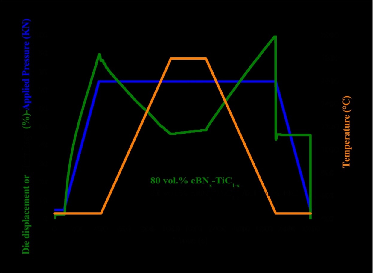
The resulting BTNC ultrafine powder mixtures were hot-pressed in graphite dies (inner diameter of 20 mm) coated with graphite shit lubricant at 1800 °C in vacuum.
The applied pressure of 75 MPa was adjusted to the powder at room temperature and kept constant throughout the hot pressing process. The pressure was applied at the beginning of the sintering process because high green density is favorable for better densification rate by reducing the pores prior to the densification during heating. The heating rate was about 10 °C/min and the dwelling time at terminal temperature was 60 min. The temperature was measured by an infrared pyrometer through a hole opened in the graphite die. Furthermore, for monitoring densification process, the shrinkage of the powder compact was measured by a displacement sensor during the hot pressing.
The dimensions of the finally hot pressed samples were about 20 mm in diameter and 3 mm in thickness.
The mixtures were loosely compacted into a graphite die of 20 mm in diameter and sintered in the vacuum (1 Pa) at various temperatures (1800 °C) using an FASPS apparatus (Lab. Sinter, FASPS-1050, Sumitomo Coal Mining Co. Ltd., Germany) (Table 1). A constant heating rate of 120 °C/min was employed, while the applied pressure was 75 MPa. The on/off time ratio of the pulsed current was set to 10/2 in each run. The maximum current reached approximately 3000 A during sintering.
Table 1. SPS synthesis parameters| Sintred Samples | T(C) | Time of the cycle (min) | Heating rate (C/min) | P (MPa) | Ar (sccm) | cBNx-TiC1-x (x=0.8)/0.1wt%. NC (d=1nm) | Current (A) |
| TiC | 1800 | 10 | 100 | 75 | 200 | 00 | 3000 |
| BT | 1800 | 10 | 100 | 75 | 200 | 00 | 3000 |
| BTNC | 1800 | 10 | 100 | 75 | 200 | 0.1 | 3000 |
The soaking time at high temperatures was within 10 min. The upper ram of the FASPS apparatus was fixed, while the displacement of the shifting lower press ram was recorded in order to analyze the synthesis and sintering. The sintered samples are presented in the Figure 2.
Figure 2.Sintered samples in the die diameter of 20 mm of BT and BTNC before and after gold metallization for microscopic observations. a- BT before metallization, b-BTNC before metallization, c-BT after etching and gold metallization, d- BTNC after etching and gold metallization.
Density of the sintered samples was measured by the Archimede’s using the densimeter type Micromiritics Accupyc 1330. The micro hardness at the top was measured by a diamond Vickers hardness tester (MVK-H1, Meter-Mitutoyo, Japan).
The indentation loads, ranging from 10 to 500 N, were applied for 15 s for each measurement. The fracture toughness was measured using the Vickers indentation by the mesuearement of the producing failler.
In this study, 06 samples for each sintering process were fabricated to obtain an average relative density and hardness.
Young’s modulus of the composites was determined by ultrasonic wave transition method measuring the velocity of ultrasonic sound waves passing through the material using an ultrasonic flaw detector (Panametrics Epoch III). The hardness and the fracture toughness were determined by the Vickers indentation method applying load of 294 N (HV30) and 490 N (HV50), by a Future Tech FLC-50VX hardness tester. For each sample 6 indentations were made and the stress intensity factor KIC was calculated from the length of Palmqvist cracks which developed during a Vickers indentation test using E. Rocha-Rangel’s equation 29. The wear resistance and the friction coefficient will be performed in the near future. The hardness (H), the elastic modulus (E) and the toughness (KIC) of the fabricated samples were measured under ambient conditions using the instrumented Vickers indentation method (ZwickRoell, ZHU 2.5 apparatus).
The impression diagonal (2a) was measured, and the hardness values were calculated according to the following relation:
Hv = (1.8544*F)/(2a)2 …..(1)
The fracture toughness was also calculated by indentation fracture (IF) method according to the equation:
KIC=0.16Hva1/2(c/a)-3/2 …...(2)
Where Hv was the Vickers hardness, a was the half-length of the indentation diagonal and c was the half-length of the median crack generated by indentation. Generally, the fracture toughness measured by IF method were fluctuating values with relatively large deviations due to the phase distribution and measurement errors of calculation. Thus a linear regression model was applied to get a reliable value of indentation fracture toughness.
To obtain the values of A, B and R2, a series of indentation loads (10 N, 50 N, 100 N, 300, 500 N) were applied to get the relations of P and c3/2
Where P is the indentation load. Through the combination of equations (1) and (2), the linear relation between P and c3/2 was obtained:
P = Ac3/2 + B (A= KIC / 0.075) …...(3)
A linear regression analysis was applied to the relations of P and c3/2 by the least square method.
To obtain the values of A and B, where A was the slope, B was the intercept.
In addition, a high determination coefficient (R2) was obtained through the linear regression model. Hence, when combined with the linear regression model, IF was shown to be an effective method in the evaluation of fracture toughness for its convenience and material saving 30.
Results and Discussion
In this research, significant progress has been made in: (1) FASPS synthesis of cBN powder (2) SPS consolidation of laboratory synthesized (and commercially supplied) cBN powder to form nanocrystalline cBN; (3) reactive-FASPS consolidation of mixed cBN -TiC powder to produce TiC-bonded cBN; (4) reactive- FASPS consolidation of mixed hBN,-TiC powder to produce TiC-bonded TiB2-TiN; and (5)reactive- FASPS processing of ceramics matrix nanocomposites (CMNCs)tools of hard TiC bonded cBN, superhard NC.
Sintering Behavior of Sintered cBNx-TiC1-x (x=0.8)-0.1 wt % NC (CMNCs) Tools
(Figure 3) shows the variation of die displacement or shrinkage, temperature and applied pressure in dependence on the heating time during the FASPS sintering. We can conclude that addition of the NC in the nanocomposite ceramics matrix tools improved the sintering behavior of the cBN x-TiC1-x (x=0.8) ceramics matrix nanocomposites (CMNCs) tools.
Figure 3.X-ray diffraction spectrum on the top surface of the sintered samples using a 20-mm diameter die, a) BT, b) BTNC (CMNCs) tools.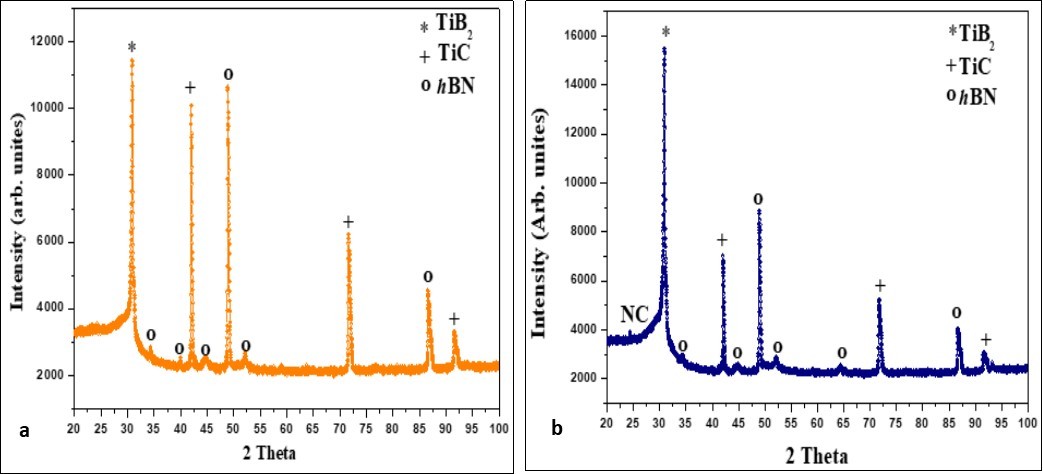
The sample is already fully densified to 98 % at T= 1800 °C at the beginning of the heating with a fast displacement of the dies and remains until the end of the heating, the temperature sensor records the displacement of the dies from T= 400 °C. The NC enhanced sample has better sintering behavior and densification than NC free.
(Figure 1) shows also the thermodilatometric measurements up to 1800 °C under vacuum in the FASPS chamber for different compositions. This experiment was performed in order to optimize the sintering temperature. As can be seen on the graph, the starting shrinkage temperature slightly increases with addition of the NC. At T= 400 °C we beginning the measurements. We will compare the dilatometric curves versus–heating time with versus temperature in the future experiments.
XRD Analysis of Sintered cBNx-TiC1-x (x=0.8) -0.1 wt% NC (CMNCs) Tools
In all two samples, XRD analysis shows that the crystallite size of the consolidated material is ~26 nm, which is about one-half the initial grain size (~56 nm) of powder. All samples are analyzed by XRD (Figure 3), and where appropriate by FESEM.. The standard XRD spectra for several phases of interest herein for the reference purpose 26. The Bravais structure of cBN, hBN, TiC, bundles of NC and TiB2 are illustrated in the Figure 4.
Figure 4.Bravais structure of the construction of (CMNCs) tools, a-cBN, b-hBN, c-TiC, and the bundles of NC with hexagonal lattice and d-TiB2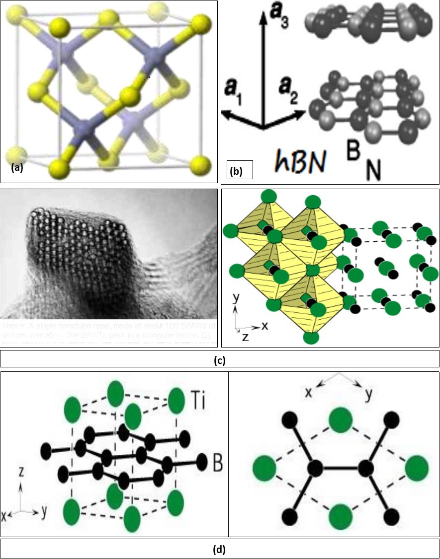
XRD analysis of the samples indicates that the only phases formed in the sample without NC are titanium carbide TiC (5 µm), with a cubic crystal structure and the transformation of the cBN to hBN crystal structure. The addition of 0.1 wt % NC has considerable effect on XRD pattern. (intensity of the XRD spectrum of the nanocomposite, which indicates that the reaction between the TiC, cBN powders and NC did happen during the sintering process in the system cBN-TiC-NC.
The X-ray diffraction investigations were carried out with diffractometer (Philips 1710) using CoKα radiation. The X-ray diffraction phase analysis and profile of diffraction line analysis were applied. After sintering of the investigated samples the following new phases (Figure 3) were formed TiB2 in the cBN-TiC system, and TiB2 in cBNx-TiC1-x (x=0.8)-0.1 wt % NC ceramics matrix nanocomposite (CMNCs) tools system. The shape of diffraction lines is a powerful tool for fine microstructure characterization. The line half-width contains information about average crystalline size and lattice defect density which can be treated as internal stored energy 27. When we compare the intensities of the tree pics located at 32, 42.5 and 50 degrees corresponding to TiB2, TiC and cBN to hBN, respectively. The highest intensity is observed for the TiB2 phase when the samples is reinforced by NC (graphitic pic located at 26 degrees) (Figure 3a and Figure 3b).The addition of NC by 0.1 wt% move the reaction of more boron atoms to react with TiC and produced TiB2 phase for additional consolidation of the (CMNCs) tools.
FESEM Microstructural Observation of Sintered cBNx-TiC1-x (x=0.8)-0.1 wt % NC (CMNCs) Tools
All three samples processed at 75 MPa are 95-98% density of cBN (ρ = 3.45 g/cm3), with balance hBN (ρ = 2.1 g/cm3). The appearance of hBN under such a high pressure is surprising.
A possible explanation is that densification via plastic deformation under high pressure is incomplete, forming micro-pores at “triple junctions «between cBN grains, which then become favorable sites for nucleation and growth of the lower density hBN.
Such behavior is most likely to occur during heat -up of the sample under high pressure. The larger amount of hBN in the sample processed at 75 MPa may be attributed to the same cause. Because of their pressure, densification via plastic deformation is less complete, leaving larger micro-pores at triple junctions of cBN that allow more hBN to form. Plastic deformation accompanied by recrystallization at points of contact between neighboring cBN particles under high pressure is a possible explanation.
However, as noted above, fully dense phase-pure cBN is not achieved able under the designated processing conditions; a small fraction of hBN is invariably formed. To eliminate cBN decomposition during FASPS, it will be necessary to investigate the use of sintering aids. The additions of TiC to cBN prevent its decomposition into hBN, probably by forming a thin surface-passivation film of Tic-base compounds. Moreover, by controlling reactions between TiC and cBN phases, fully dense composite structures can be obtained, comprising high fractions of super hard cBN particles cemented together with hard TiB2composites.By the addition of 0.1 wt% of NC we obtain super hard ceramics matrix nanocomposites (CMNCs) tools. When such composite structures contain residual un-reacted TiC, there is the prospect of enhanced toughness, while retaining high hardness, stiffness, To summarize, fully dense nanocrystalline cBN-TiC can be produced by FASPS processing, but the formation of a minor fraction of hBN seems unavoidable.
This is unfortunate, since the presence of even a small amount of hBN, particularly at nano grain boundaries, must adversely affect fracture toughness. On the other hand, an addition of TiC to cBN provides a route to produce fully dense cBN-based composites with hBN, and thus potentially enhance mechanical performance. The FESEM microstructures of samples with following compositions:
The FESEM microstructures (Figure 5) revealed that the ceramics matrix nanocomposites (CMNCs)) tools has good density of the binder less phases in the final structure of the products. The high magnification representative microstructure of the sample without NC (Figure 5a-b-k-i) consists of large hBN (dark) grains (Figure 5 e-f-h) and TiC (gray) (Figure 5c-d) particle sintered together and remaining not transformed and unreached cBN (Figure 5k-i)The addition of 0.1 wt % N C (Figure 5e-f) to the reaction changed the morphology of hBN from slightly finer grains with near spherical morphology to the large plate like grains. Figure 5e-d, shown the NC in the matrix intra grain boundaries TiC and hBN particle forming the interface with different orientations. The mechanical properties are improved by both phases and grain boundaries. This contributed to the increasing of the Vickers microhardness. In the Figure 5k-i is presented the typical of the loss of NC identified by the pore like structure (canneaux). High magnification images of the starting ultrafine powder of NC and sintered titanium carbide (TiC) are presented in Figure 5a-b and c-d.
Figure 5.High magnification micro structural representative FESEM image of BT and BTNC polished and etched surface for the sintered samples using a 20 mm diameter dieof the sintered samples
Relative Density Sintered cBNx-TiC1-x (x=0.8)-0.1 wt % NC (CMNCs) Tools
The influence of the addition of the reinfort of carbon nnotubes on the relaties density of sintered cBNx-TiC1-x (x=0.8) nanocomposites is shown in Table 2. The theoritical density of the nanocomposite used for obtaining relative density was calculated using a rule of mixture, using the densities of two constituent phase (ρhBN= 2.1 g/cm3, ρ cBN = 3.45 g/cm3, ρTiC = 4.50 g/cm3, ρNC= 2.25 g/cm3) with the given SPS processing parameters, the cBN x-TiC1-x (x=0.8)with and without 0.1 wt % NC sample exhibited best densification with relative density greater than 97.5%, with the similar processing parameters with addition ofcarbon nanotubes. The relative density increases with the addition of NC. The cBNx-TiC1-x(x=0.8)-0.1 wt % NC nanocomposites at T=1800 °C exhibited relative density of about 98.5%.Depending on the final density to be achieved, the FASPS operating condition were properly chosen, that is, 1800 °C, 75 MPa for 10 min, to obtain a highest relative density for the nanocomposites cBNx-TiC1-x (x=0.8), densecBNx-TiC1-x (x=0.8)-0.1 wt % NC, TiC for zero compacts porosity, 97.5, 98.06, and 94.06, respectively.
Table 2. Basic physical–mechanical properties of the samples obtained by FASPS sintering| Sintred samples | TiC | BT | BTNC |
|---|---|---|---|
| Density (relative density) g/cm3 (%) | 94.60 | 97.50 | 98.50 |
| Young’s modulus (relative Young’s) GPa (%) | 439.4 | 865.6 | 910.8 |
In the Figure 6, the microstructural representation and EDS analysis displays elemental analyses of the various regions of the sintered samples. Secondary electron image, atomic concentration cartographies of B, Ti, N and C are also illustrated. EDS spectra and was used to determine the elemental composition of the different regions in the sample with NC addition and are presented at the Figure 7.
Figure 6.Microstructural representation and EDS maps of BTNC sample analysis displays elemental analyses of the various regions of the sintered samples. Secondary electron image, atomic concentration cartographies of B, Ti, N and C of polished and etched surface for the sintered samples
Figure 7.EDX spectra in different region of BT and BTNC polished and etched surface for the sintered samples using a 20-mm diameter die of the sintered samples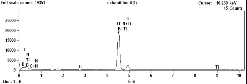
The 1.5 % porosity of the sample cBNx-TiC1-x (x=0.8)-0.1 wt % NC exhibited a round microstructure with high ductility, 98.5 %.
Also, the easy sledding of their walls when attached by weak van der Waals force of coalesced MWCNTs can probably increases the relative density. The density of the sintered samples was determined using the Archimedes helium immersion method.
Vickers Micro Hardness and Fracture Toughness (KIC) of the Sintered cBNx-TiC1-x (x=0.8)-0.1 wt % NC (CMNCs)Tools
According to the above results, it can be concluded that the Vickers hardness has been improved by adding NC and enhanced with the fracture toughness value giving a better ductility for the reinforced NC samples. Figure 8 shows the hardness as a function of the applied indentation load for the same sample. At lower loads, the micro hardness reaches a low hardness a constant value of 47.55, 18 and 35.26 GPa at HV50 for reinforced cBNx-TiC1-x (x=0.8)-0.1 wt % NC, TiC, and unreinforced cBNx-TiC1-x (x=0.8), nanocomposites with CN, respectively.
Figure 8.Representation the variation of Vickers micro hardness fonction of the indentation leads of the sintered samples using a 20-mm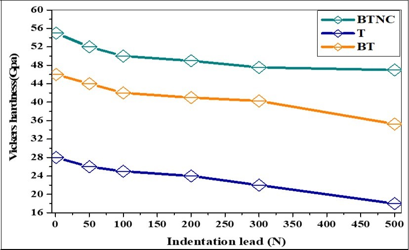
In the present study, the high hardness of the FASPS synthesized sample containing nanocomposite cBNx-TiC1-x (x=0.8)-0.1 wt % NC at T= 1800 °C may be attributed to its high density (98.5% from theoretical).
(Figure 8) present the variation of Vickers micro hardness of cBN x-TiC1-x (x=0.8)-0.1 wt % NC nanocomposites with NC reinforcement content at T= 1800 °C with the indentation lead. The microhardness of the nanocomposites increased almost linearly with NC reinforcement and with addition cBN (80 vol. %) content in TiC hard carbide. The hardness of CN (28–30 GPa) is nearly 2 times the previously reported values of hardness of TiC (18 GPa). For the nearly single phase hBN sintered (FASPS) in this investigation, the micro hardness was found to be 30 GPa (measured with indentation load of 300 N), which is higher than the previously reported hardness values for hexagonal in the literature. While the higher hardness of the cBNx-TiC1-x (x=0.8)-0.1 wt % NC nanocomposite sample could be due to a minor amount of NC intragranular reinforced TiC grain phase in the nanocompositecBNx-TiC1-x (x=0.8).
The highest Vickers micro hardness in the range of about 55 GPa was found for lower loads (10 N). A slight increase in average hardness have been obtained from nanocomposites prepared by FASPS sintering of cBNx-TiC1-x (x=0.8)-0.1 wt % NC at T=1800 °C exhibited highest hardness of about 47.55 GPa was found for lower loads (500 N). (Figure 6), Itis considered that cBN 20 vol% TiC with the remaining 0.1 wt% NC act as reinforcements play the major role in the consolidation of the products.
The best product contained cBNx-TiC1-x (x=0.8)-0.1 wt % NC which was sintered at 1800 °C, 75 MPa for 10 min. The Vickers hardness of cBN-TiC1-x (x=0.8) increases with NC incorporation in the matrix (Figure 8).
With this addition in the matrix, the electro discharge among powders may lead to self-heating and purification of the particle surface, resulting in activation of the formation of the nanocomposites.
Fracture Toughness (KIC) of the Sintered cBNx-TiC1-x(x=0.8)-0.1 wt% NC (CMNCs) Tools
The relevant data were listed in Table 3. In Figure 9, a linear regression analysis was applied to the relations of P and c3/2 by the least square method.
Table 3. Data of Vickers indentation cracks and fracture toughness (KIC)
Figure 9.Correlation between the applied load P and half-length of median crack c3/2of polished and etched surface for the sintered samples using the (IF) method.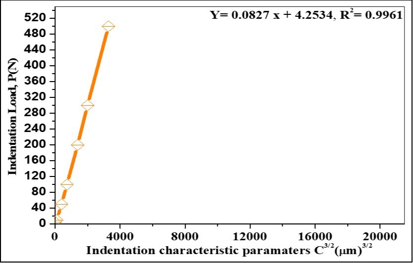
As a result, the calculated slope A and intercept B were 0.0827 and 4.2534, respectively. The indentation fracture toughness was calculated to be 12.30 MPa m1/2 for cBNx-TiC1-x (x=0.8) -0.1 wt % NC ceramics matrix (CMNCs) tools with excellent wear resistant will be confirmed.
The addition of NC plays a important binder less role (the ductility) in the propagation of failler in this nanocomposites and thus enhance the fracture toughness in comparison with his higher hardness In addition, a high determination coefficient (R2) of 0.9961 was obtained through the linear regression model 30. IF (indentation fracture) was shown to be an effective method in the evaluation of fracture toughness for its convenience and material saving.
Raman Spectroscopy of cBNx-TiC1-x (x=0.8)-0.1 wt % NC (CMNCs)Tools
In the Figure 10 is presented the Raman response of the nanocomposites cBNx-TiC1-x (x=0.8)-0.1 wt % NC, TiC and cBNx-TiC1-x (x=0.8) with laser excited by λexc=244 nm. The transition of cBN to hBN are detected by the vibration frequency response by tree vibration mode of the hexagonal lattice longitudinal (LO), transversal (TO) and E2garround the 1447 for E2g, 2142 for 2LA(K), 2656 for 2TO(KM) and 2887, 3060 cm-1for 2LO(T) respectively, according to 28. The reinforced phase of the binder less NC is localized in the typical frequency of G and D mode at 1351and (1524, 1594) cm-1, respectively. The Raman spectra confirm the XRD investigations.
Figure 10.Raman spectra of the BTNC sintered sample using a 20-mm diameter die.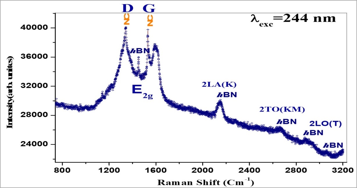
Conclusions
We have succefull produced (CMNCs)tools by FASPS with several quantities of TiC ultrafine powder were added to the FASPS sintreddensecBNx-TiC1-x(x=0.8)-0.100 wt% NC (CMNCs)tools at 1800 °C under a pressure of 75 MPa for 10 min in high vacuum protection. Phase analysis using XRD and EDX indicated that binderless fines powders hBN, TiC and TiB2 and un-reacted binder phase NC and untransformed cBN were the main products. Microstructural observations by FESEM showed that the effect of NC as binder phase make interface intra TiC grains and good physical (relative density) and mechanical properties (Vickers hardness, yung’s modulus, fluxual strain, and fracture tougness) of nanocomposite are obtain for cBNx-TiC1-x (x=0.8)-0.1 wt % NC, FASPS produced samples .The loss of NC during or conversion of NC the sintering process are fixed by the pore like structure in the FESEM pictures.
The best density 98.5 % from the theoretical and ductility of the nanocomposites ceramics matrix tools cBNx-TiC1-x (x=0.8)-0.1 wt % NC is obtain with the addition of the binderlessreinfort phase NC and 20 vol. % of TiC.
The fracture toughness is enhanced (ductil nanocomposite) KIC=12.24 MPa m1/2 in comparison with his highest Vickers hardness. The Raman response confirms the XRD investigations of the sintered samples Furthers measurement will be carried out with the nanoindentation technics.
Furthers studies also will be performed with variation of the graphite die diameter, to control the NC content in the nanocomposites ceramics matrix toolscBNx-TiC1-x (x=0.8)-0.1 wt % NC. By FASPS, the extensive volume expansion as a function of the pressure will occur. We will be finding efficiency methods for mixing of NC in (CMNCs)tools; NC will be metalized before mixing and sintering for minimizing theirs loss.
For guidance of NC we are planning to install a magnetic field device around the temperature FASPS chamber to give a NC orientation in the matrix to get better properties of manufactured (CMNCs) tools.
Acknowledgements
This project is funded by the Algerian ministerium of scientifique research. We are grateful to Aurélien Lepeutrec and Ibrahim Itaalit (LUSAC, EA 4253, Université de Caen Basse-Normandie (UCBN), (Cherbourg-Octeville, France) for the helps in the FESEM. Many thanks go to Pr. Dominique Vrel from LIMHP, Paris, France and Pr. Kamel Loucif from the University of Setif, Algeria for the XRD investigations.
Without forgetting Yannick for the accuracy measurements in Resonant Raman Scattering Spectroscopy.
References
- 11.Angseryd J, Elfwing M, Olsson E, Andrén H-O. (2009) . , Int. J. Refract. Metals Hard Mater 27, 249-255.
- 24.Yazu S, Kohno Y, Sato S, Hara A. (1981) . Mod. Dev. Powder Metall. Standards and Technology under project MP/14: 363-371.
- 28.Reich S, A C Ferrari, Arenal R, Loiseau A, Bello I et al. (2005) Resonant Raman scattering in cubic and hexagonal boron nitride. , Phys. Rev. B 71, 205.